Most physical computing projects I see stall in the same place. The idea is good, the board is on the desk, the sensor is wired, and the numbers on screen jump around for no reason anyone can explain. I hit that wall too. What got me past it was not a better library. It was a semester of building sensor circuits by hand, where I had to understand what a sensor actually puts out before any code touched it.
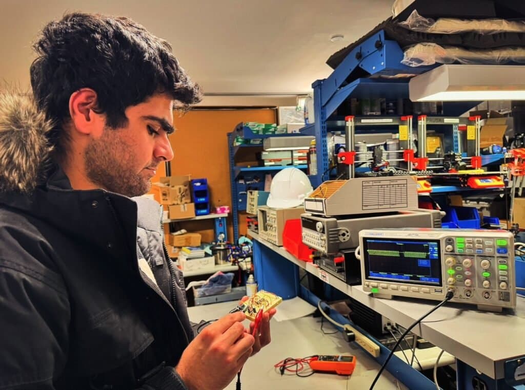
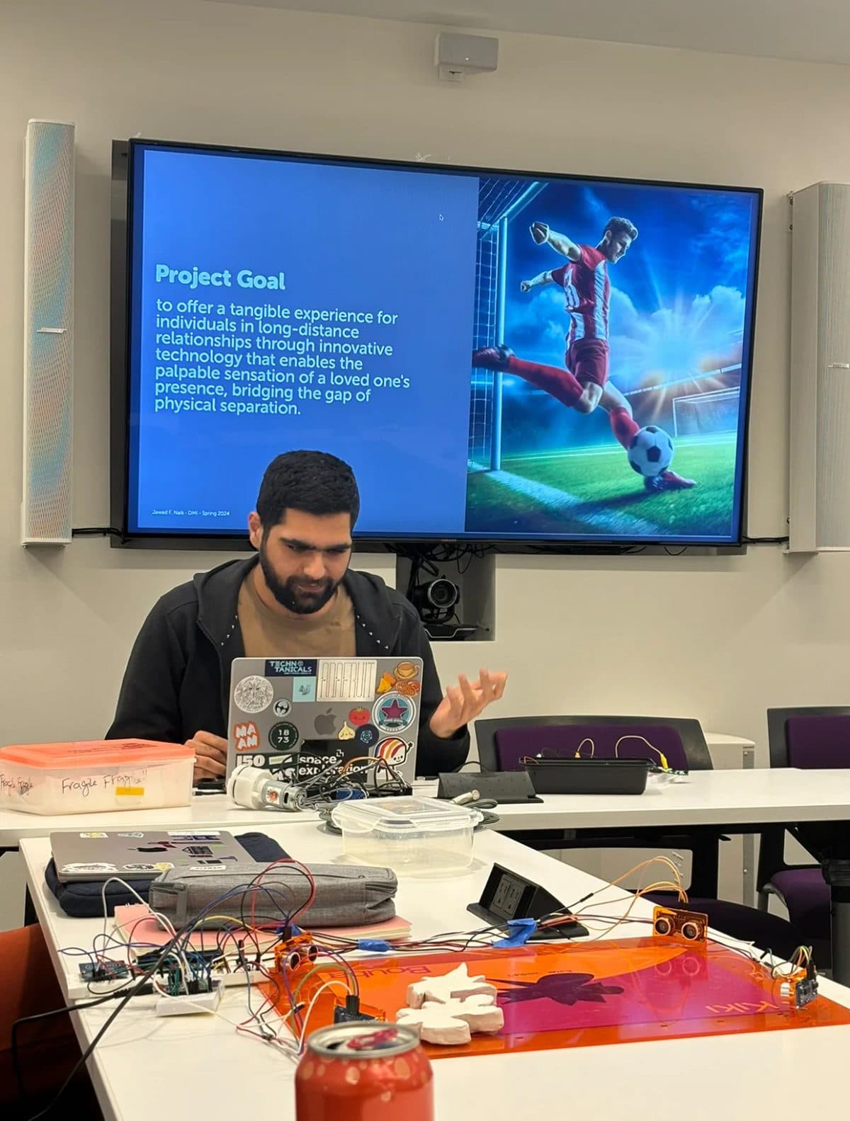
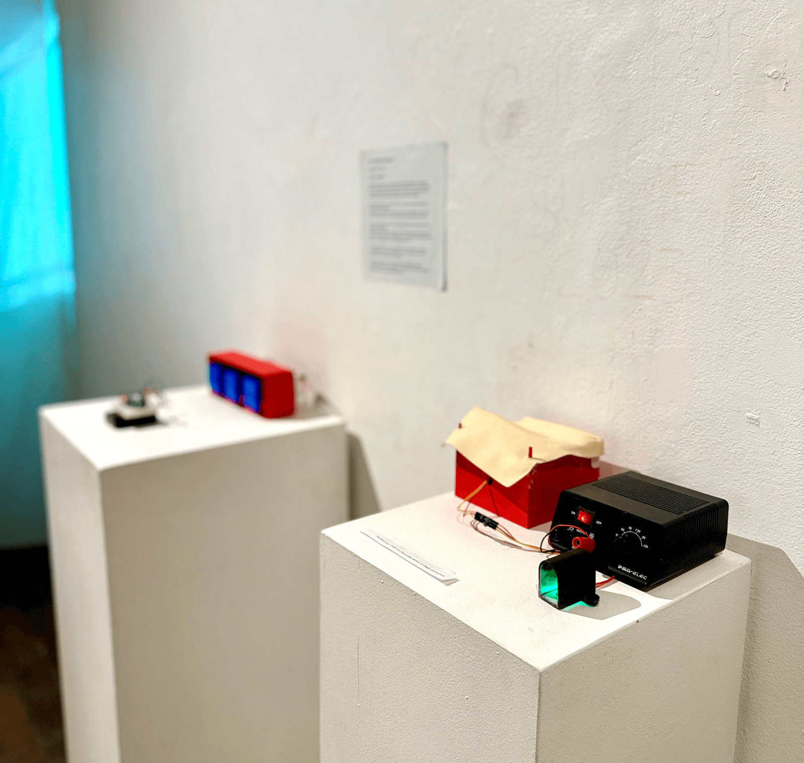
I took Sensor Technologies for Interactive Environments with the Responsive Environments group at the MIT Media Lab as a crossover registration during my MFA. The course, which MIT also publishes as MAS.836 on OpenCourseWare, starts with electronics for signal conditioning and then works through sensor families: pressure, strain, proximity, thermal, electric and magnetic field, optical, acoustic, inertial and bioelectric. My coursework was breadboards, filter circuits, a capacitive touch plate and a lot of time with a multimeter. My final project was the sensing rig for Huggables. This post is what that semester changed about how I build.
If you want the beginner kit list and your first sketch, start with my Arduino prototyping guide for designers. This one goes a layer down, into the electrical side most tutorials skip.
Lesson 1: A sensor gives you a voltage, not a value
Before the course I thought of a sensor as something that "returns a number." It doesn't. Nearly every simple sensor changes a voltage, a resistance or a capacitance, and your circuit has to turn that change into a voltage the board can read. The number comes last.
On a classic Arduino, the board's analog-to-digital converter does that last step. Arduino's own analogRead() reference says the default resolution is 10 bits, mapping 0 V to the operating voltage onto integers from 0 to 1023, which on a 5 V board is about 4.9 mV per step. That one fact explains a lot of disappointment:
- If your sensor only swings a few tens of millivolts, you are using a handful of those 1,024 steps. The reading will look coarse and noisy no matter how you smooth it in code.
- If your sensor swings past the board's voltage, you clip at 1023 and lose everything above it.
- The fix for both is in the circuit: pick the right resistor for a voltage divider, or amplify a small signal so it fills more of the range.
The practical habit I took away: before writing code, sketch the circuit and write down the expected voltage at rest and at the extreme. If you can't predict those two numbers, you don't yet understand the sensor, and the code will inherit that confusion.
Lesson 2: An unconnected pin is not zero
The most common "haunted" prototype is a floating input. Arduino's documentation is blunt about it. An analog pin with nothing connected will fluctuate based on other inputs and even how close your hand is to the board. A digital pin left open will randomly return HIGH or LOW, which is why buttons and switches need a pull-up or pull-down resistor to hold the pin at a known level.
Arduino boards include internal pull-ups you can switch on with pinMode(pin, INPUT_PULLUP). The digital pins guide puts them at 20 kΩ to 50 kΩ on most AVR boards. With a pull-up, the pin reads HIGH when the switch is open and LOW when it is pressed, so your logic is inverted. Write that on a sticky note. I have lost an evening to it.
The floating pin taught me something bigger than resistors. That same sensitivity to a nearby hand is how capacitive sensing works. In the course I wired a bare metal plate into a capacitive touch circuit, and the behavior that ruins a button reading became the whole interaction: the plate responded to a hand on it. Noise is often just a signal you didn't design for.
Lesson 3: Fix the signal before you fix the code
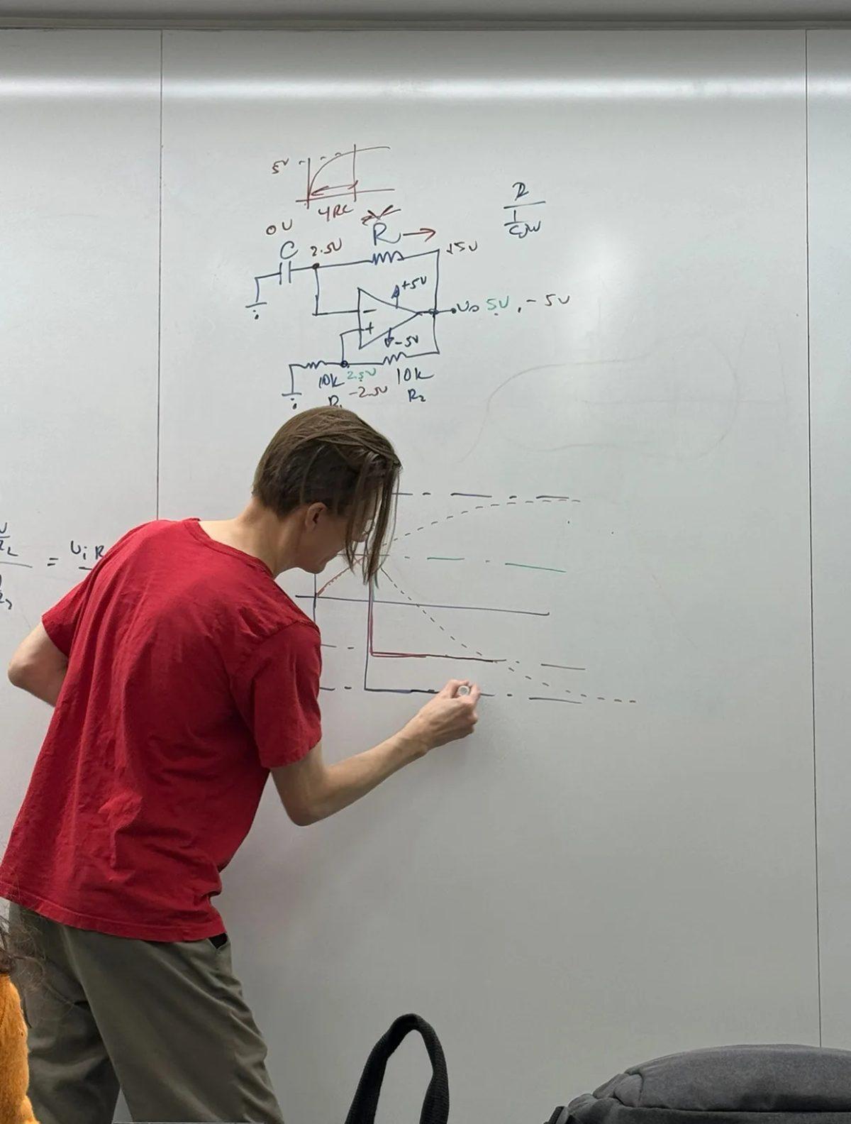
A big part of the course was signal conditioning, and it is the part I now think designers undervalue most. Several of my lab circuits were analog filters on a breadboard, built and then checked on an oscilloscope against the hand calculations in my notebook.
Software smoothing, like the running average in my Arduino guide, is fine for gentle jitter. But it has limits:
- It adds lag. Heavy averaging makes a heartbeat arrive late, and in something like Huggables, a late pulse feels fake.
- It can't recover what the ADC never saw. If the signal is too small or clipped, no filter in code brings it back.
- It can't separate overlapping noise well when the noise and the signal live in similar ranges. A filter designed around the signal's speed does better.
My rule now: if the problem is "it flickers a bit," smooth in code. If the problem is "I can't see the thing I'm trying to measure," go back to the circuit, gain or filtering, or a different sensor.
Lesson 4: Measure with instruments, not just Serial.print
Printing values to the Serial Monitor tells you what the board thinks. A multimeter tells you what the wire is actually doing. Those two disagree more often than you'd expect, and the disagreement is usually the bug: a loose jumper, a resistor one color band off, a sensor powered from the wrong rail.
The order I debug in now, every time:
- Power. Measure supply voltage at the sensor itself, not at the board.
- Rest state. Measure the signal pin with the sensor untouched. Does it match the number you predicted in Lesson 1?
- Extreme state. Press, cover, heat or shake it. Does the voltage move the direction and distance you expected?
- Only then the code. Print raw values, before any mapping or smoothing, and check they agree with the meter.
An oscilloscope is a luxury for most hobby setups, but the Arduino IDE's Serial Plotter gets you a rough version of the same view for slow signals. Watching a waveform instead of a scrolling column of numbers is where patterns, like a breathing rhythm or periodic interference, become obvious.
Lesson 5: Choose the sensing modality from the body, not the catalog
The course walked through sensor families one by one. The lesson I took was to choose by what the person or space actually does, then pick the family that can feel it. Here is the cheat sheet I use when planning physical computing projects. It is my own working summary, not a spec sheet.
| What you want to sense | Sensor family to consider | What usually bites you |
|---|---|---|
| A touch or a squeeze | Capacitive pads, force sensitive resistors | Capacitive readings shift with humidity, grounding and cable length; FSRs are good for "harder vs softer," weak for exact force |
| Movement, tilt, a tap, breathing against an object | Accelerometer (inertial) | Gravity is always in the reading; you need a baseline and change over time, not raw values |
| Someone approaching | Ultrasonic or infrared proximity | Soft, angled or dark surfaces reflect badly; readings drop out at edges |
| Warmth, body or room temperature | Thermistor or digital temperature sensor | Slow to respond; board heat and your own hand skew it |
| Heartbeat | Optical pulse sensor | Very sensitive to finger pressure, movement and ambient light |
| Sound level or voice | Microphone | Room noise; level is easy, meaning is hard |
For Huggables I needed heart rate, breathing and temperature, and the choices followed this logic. Breathing moves the body against the pillow, so motion sensing could read it. Pulse needed a dedicated optical sensor clipped on. Temperature could come from a simple onboard part. Each of those has its own failure mode, and knowing them in advance shaped where the sensors sat and how I filtered them.
Lesson 6: Prototype on a board that already has the sensors
For the final project I didn't wire everything from scratch. I used a Circuit Playground, which made it possible to test the whole sensing idea in days. Adafruit lists the classic board with a LIS3DH accelerometer, a thermistor, a light sensor, a MEMS microphone and eight pads that work as capacitive touch inputs, all on one round board. I used the onboard accelerometer for breathing, the onboard temperature sensing, and a pulse sensor attached with alligator clips, then averaged the readings in Arduino code before sending them on.
The trade-off is honest: an all-in-one board puts every sensor in one spot, which is rarely where the body is. It's perfect for proving the interaction and wrong for the final object. Once the idea worked, the next questions were physical ones, like where a sensor sits inside soft material and how warmth from the electronics affects a temperature reading. I wrote about those material lessons in designing tangible technology with Huggables.
Lesson 7: Know when a Raspberry Pi is the wrong tool
People ask me whether to start with Arduino or Raspberry Pi. For reading sensors directly, the electrical details decide it. Raspberry Pi's official hardware documentation describes its GPIO as 3.3 V pins, with inputs that are 3.3 V tolerant, and warns not to use 5 V for 3.3 V components. The GPIO header also has no analog inputs, so an analog sensor like a thermistor or a force sensitive resistor needs an external analog-to-digital converter.
That points to a simple split I still use:
- Microcontroller (Arduino, Circuit Playground) for reading sensors, tight timing and driving motors, lights or heaters through the right driver.
- A full computer (a Pi or a laptop) for screens, networking, media, heavier processing and visualization.
- Often both, with the microcontroller doing sensing and sending clean numbers over serial to the computer.
That last pattern is exactly what my final project did. The Circuit Playground read the sensors and a Processing sketch on the laptop drew a shape that changed color and size with each reading. If you want to try the visual half in a browser, my p5.js starter for designers covers it.
Lesson 8: Sense and respond at the same time
The moment a project has more than one sensor or more than one output, delay() becomes the enemy. Arduino's Blink Without Delay example explains why: the program pauses during a delay, so nothing else can be read or updated. The fix is to note the time with millis() and check on every loop whether each task is due.
This matters more in sensing projects than in blinking-LED tutorials. A pulse sensor needs frequent sampling, temperature barely changes, and an LED animation wants smooth steps. Each task gets its own timer. When I restructured my code that way, the jitter I'd blamed on the sensors mostly disappeared, because the board was finally reading them on schedule.
When not to build the hardware at all
The course made me more willing to build sensors and also more honest about when not to. Skip custom hardware when:
- A phone already has the sensor. Motion, sound, light and touch are in every phone. If the experience works on a screen, test it there first.
- You need medical accuracy. A hobby pulse sensor is fine for art and feeling. It is not a medical device, and you shouldn't design anything that someone will rely on for health decisions around one.
- Nobody will maintain it. Installations break: cables pull, batteries die, sensors drift. If there's no plan for upkeep, a simpler piece may serve people better.
- The interaction isn't defined yet. Hardware makes vague ideas expensive. Write the one-sentence experience first.
A checklist before your next physical computing project
- One sentence describing what is sensed, what is decided and what is expressed.
- Sensor family chosen from the body or space, with its known failure mode written down.
- Predicted voltage at rest and at the extreme, checked against your board's range.
- Every input has a pull-up, pull-down or a driven signal. Nothing floats.
- Signal problems fixed in the circuit first, then smoothed lightly in code.
- Readings checked with a multimeter before you trust Serial output.
- Logic level checked: 5 V parts never wired straight to 3.3 V pins.
- Code uses
millis()timers, notdelay(), once there is more than one task. - A plan for what happens when a sensor fails or disconnects.
Frequently asked questions
Do I need an engineering background for physical computing projects?
No. I came from visual communication and dynamic media. You do need patience with the electrical basics in this post: voltage, pull-ups and measuring before guessing. Those few ideas solve most beginner problems.
Is Arduino or Raspberry Pi better for sensors?
For reading analog sensors directly, a microcontroller like Arduino is simpler, because the Raspberry Pi's GPIO has no analog inputs and runs at 3.3 V. For anything with a screen, networking or heavy processing, a Pi or laptop is better. Many projects use both.
Why do my sensor readings jump around?
Check, in order: a floating pin with no pull-up or pull-down, a loose connection, a signal too small for the ADC's range, and code blocking with delay(). Smoothing in code should be the last fix, not the first.
What's a good first sensor project?
A capacitive touch pad or a light sensor driving one LED. Both teach the rest state versus extreme state habit, and both work on a Circuit Playground with no extra parts.
You can see the circuits and the Huggables sensing rig in my MIT coursework. If you're planning an interactive installation, a sensor-driven object or a connected prototype and want a second pair of eyes on the sensing plan, tell me what you're building. I'm happy to help you get from a jumpy reading to something people can feel.